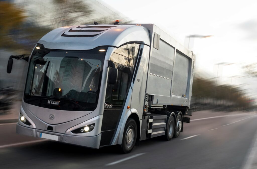
Irizar Group ie Truck
Irizar Group ie Truck

Developing heavy EVs for urban applications, where regulations on emissions and noise are the strictest of any operating environment, requires a wealth of research and experience in electrical, mechanical, software and other branches of engineering. The Irizar Group has these in spades. In addition to the hundreds of electric buses it has supplied across Europe, its newest vehicle, the ie truck, developed jointly with FCC Medio Ambiente, is one of the first of its kind to be produced in southern Europe.
The truck currently comes in two varieties. One is a four-wheeled, two-axle model with a maximum weight of 10.5 t, a battery of up to 300 kWh capacity (offering a range of up to 250 km between charges) that takes up to 2 hours to recharge on a 150 kW input, and a 160 kW electric motor. The other is a six-wheel, three-axle model powered by a 240 kW e-motor. It has the same range between charges, enabled by a battery with up to 400 kWh (with a 3-hour charge time at 150 kW).
Notably, both trucks have low-floor cabins – an unusual feature for trucks of this size and weight – with a cabin access step 37 cm off the ground and a cabin top height of around 366 cm. Also, both can be supplied with a fully electric powertrain or a hybrid-electric range extender. The latter incorporates a series-hybrid arrangement, in which the battery packs are intermittently charged by a generator driven by a compressed natural gas (CNG) engine.
The impetus for developing the ie truck dates back to late 2014, when Irizar was in talks with Spanish urban waste management multinational FCC Medio Ambiente. The latter has considerable experience in making equipment for refuse collection and other municipal services, and wanted to move to EVs to reduce pollution and noise.
Josu Letona, new developments manager at Irizar, says, “Our experience in making fully electric buses drew FCC’s interest, not only for making powertrains for heavy vehicles that weren’t too loud for urban work but because they also wanted a refuse truck designed with a low-floor cabin and right-hand door. These reduce the number of workers suffering injuries when getting in and out of conventional trucks, and ensure direct visibility of pedestrians and cyclists.
“All our buses combine electric powertrains with precisely the type of cabins they were looking for, and the load requirements are similar because both buses and refuse trucks consist of very large and changing masses, with frequent stopping and starting motions, so our knowledge was a good match for their needs.”
The first prototypes were assembled and tested in Irizar’s workshops in 2018, and in 2019 the company’s engineers put them through road testing. That included trials of the bin loader and compactor systems, as well as putting the truck through certification so that it could be made commercially available in 2020.
“A truck with a bin loader and compactor is the most challenging type of heavy road vehicle to engineer, because you have to get so much just right in terms of power consumption, noise minimisation, cabin design and so many other factors in what is a complicated system,” Letona says.
“We’ve now carried out waste management duties with the truck across more than 12 cities throughout Europe. But it doesn’t have to be a waste truck – it could just as easily be used for logistics, road sweeping, cement mixing, as a crane or other urban jobs. We’re happy to develop a new payload for the chassis and make adjustments to the powertrain to optimise the truck to suit customer requirements.”
Systems layout
Having a low floor means that most of the powertrain components are positioned behind the cabin, with none beneath it. The ie truck is designed to carry four workers, with three passenger seats in the cabin besides the driver’s seat, in front of which is of course the driver’s dashboard and controls.
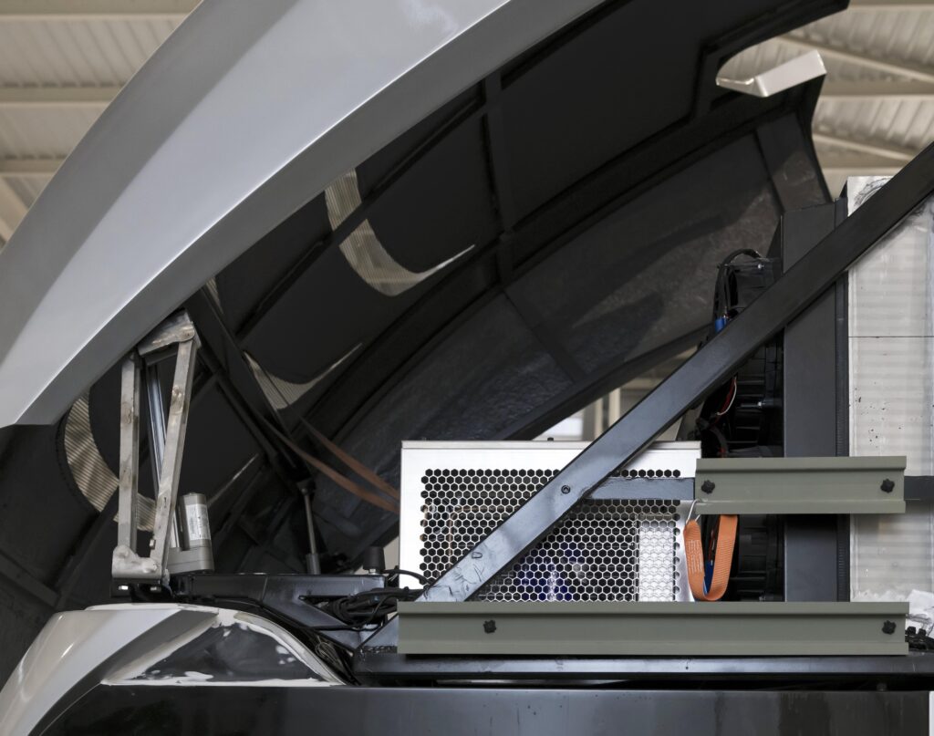
Atop the cabin is a covered inlet. As the ie truck drives forwards, fresh air flows into its ducts, inside of which are the cooling radiators and fans for the vehicle’s HVAC and thermal management systems.
Directly behind the cabin is a tall structure of key electrical and electronic subsystems, which Irizar refers to as a components cradle or components tower. These include the air compressor for the brakes and suspension, as well as the vehicle’s power electronics and ECUs, and the electric motor for driving the refuse collector’s hydraulics.
At the bottom of the cabin is a combustion engine and generator if the CNG-hybrid option has been incorporated; if not, additional battery packs are fitted instead. A high-voltage distribution unit is also installed here as a switchboard between the battery packs and electrical loads.
Specifications
ie truck
Battery-electric or CNG series hybrid
Permanent magnet AC motor
NMC pouch-type cells
4 x 2 wheel
Two-axle
Weight: 10.5 t
Maximum energy: 340 kWh
Maximum range: 250 km
Maximum power: 160 kW
Maximum operating torque: 3000 Nm
Charging time: Up to 2 hours at 150 kW
6 x 2 wheel
Three-axle
Weight: 12.5 t
Maximum energy: 340 kWh
Maximum range: 250 km
Maximum power: 240 kW
Maximum operating torque: 3600 Nm
“The architecture is very similar across all the ie trucks, whether hybrid or fully electric,” Letona adds. “If we made a hydrogen-powered version, hypothetically that too would change very little.”
A thin corridor behind the driver and passenger seat enables easy access to the components for quick inspections or lengthier maintenance tasks, or the side panels of the cabin can be opened if access of a different kind is required. Either way, this removes the need to forward-tilt the entire cabin for maintenance access, as some conventional trucks are designed to do.
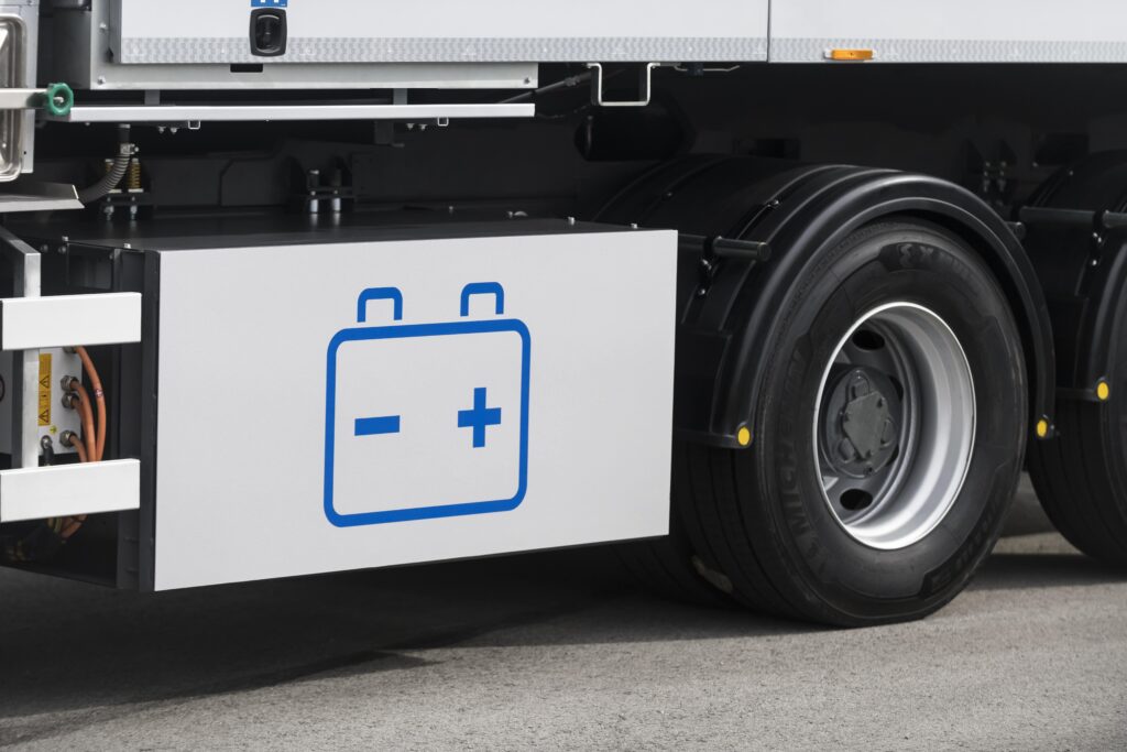
The batteries are installed beneath the chassis, although their exact placement can vary depending on customer preferences. Irizar says most manufacturers integrate them on the sides, exposing them to collisions, so the ie truck has been designed to accommodate batteries centrally between the main beams for safer operations; some batteries can be installed on the sides however, if greater energy capacity is requested.
“Side battery placement works well with standard-issue truck parts and configurations that maintenance and body-build engineers are used to,” Letona says.
The main structural material used for most of the ie truck is carbon steel with a high abrasion resistance, given the high concentration of sharp fragments of some refuse the vehicle’s insides and outsides are likely to be in contact with, and the heavy mass to be carried. R29 crash tests are needed for safety certification, rendering carbon or glass fibre composites unsuitable.
Control and power architecture
Most of the ie truck’s subsystems have their own ECU for receiving and processing commands at the local level, and transmitting operating telemetry.
High-level control and data management is handled by two main ECUs. The first is the electric vehicle control unit (EVCU), which is responsible for sending traction and steering commands from the driver’s wheel and pedals to the inverter and motor, and verifying speed and turning data to the driver.
It also controls all the other permanent magnet AC machines on board – that is, the hybrid generator (if present), the air compressor for braking, and the electric power take-off (ePTO) motors for actuating the refuse system’s hydraulics. Lastly, it also communicates with all components to validate their performance and provide alerts to the driver if a subsystem is behaving sub-optimally.
The EVCU measures 247 x 206 x 87 mm and weighs about 1 kg, drawing 1.5 A during normal operations within an IP67-rated enclosure. It features 50 analogue input channels and 24 digital inputs for data and signals from sensors, with eight analogue inputs and 25 digital outputs for delivering commands (one of those being a 15 A output, the rest 4 A), plus three CAN I/Os, as well as Ethernet and wi-fi for rapid data comms.
The second high-level controller is the energy management ECU, which monitors and if necessary adjusts energy storage and transmission across the vehicle. It looks after the high-voltage power distribution, battery management and thermal management.
“All the ECUs communicate with each other via CAN bus, with our architecture following the J1939 SAE standard,” Letona adds.
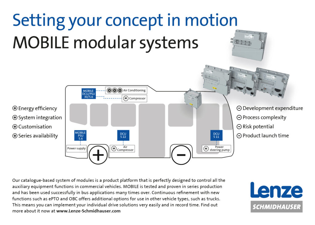
The ECUs, steering pump, driver dashboard systems, and the HVAC and liquid coolant pumps and fans are powered over a 24 V bus. A DC-DC converter in the components tower steps down the HV input from the main batteries, in order to charge a 24 V battery that delivers a regulated power output for the electronics and other systems.
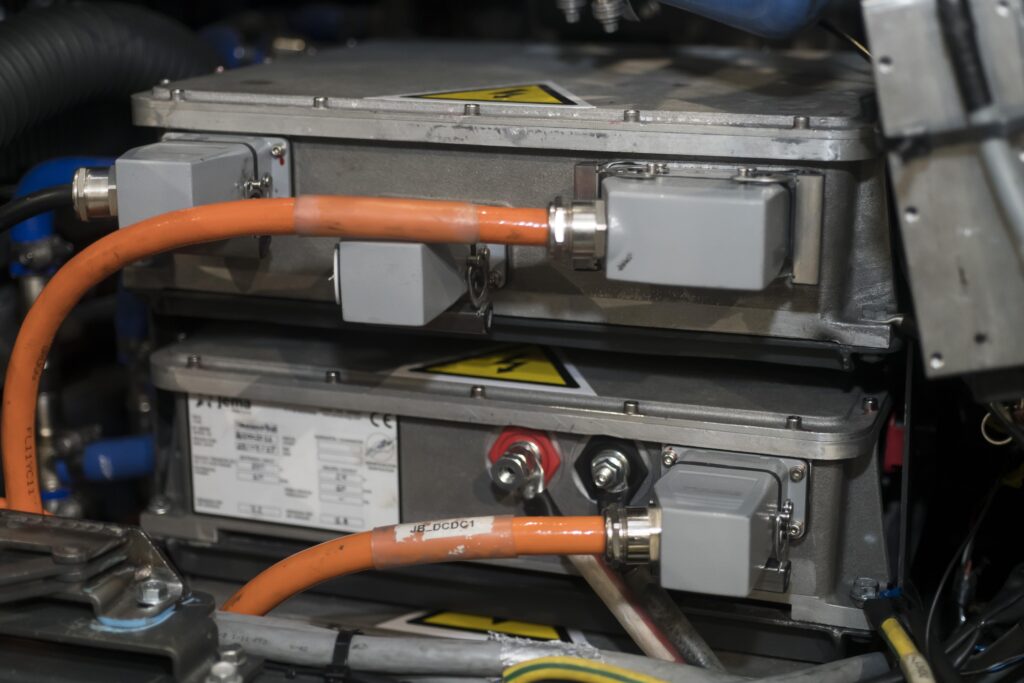
That DC-DC is referred to as the Mobile PSU (Power Supply Unit). It is rated to run on a maximum input of 850 V DC – 800 V as standard – outputting a supply between 30 and 16 V at a typical continuous current of 200 A, with a nominal efficiency of 93%.
The tower also contains a DC-AC converter for driving the 400 V AC compressor for the brakes and suspension systems.
Traction motors
Different motor sizes are available to suit the exact power requirements and axle counts for each customer. These are referred to internally as the ‘S’, ‘M’ and ‘L’ – small, medium and large – motors.
“For the two-axle truck, we typically use one of our S or M motors, and for the three-axle truck, either M or L configurations will be installed,” Letona says. “The S-size motor is rated to 160 kW nominal output, the M-size to 236 kW and the L-size to 350 kW, with all ratings performed at 3500 rpm. As for torque, we can go from 2500 Nm on the smallest motor to 4400 Nm on the biggest, with the M-type producing 3600 Nm.
“High torque and modularity are extremely important to our motor design targets,” he adds. “We’re based in the Basque Country, in the north of Spain, which is very hilly and even mountainous in places.
“It’s on local roads under these conditions that we start road-testing new vehicles, so we know how important high torque can be for driving EVs up and down slopes, and also that torque requirements can vary a lot between different cities and villages. That means we don’t offer customers only one motor configuration if we want to right-size each product cost-effectively.”
Regardless of the size chosen, the e-motor is installed under the vehicle near the drive axle. The two are connected via a short shaft (around 0.5 m long), eliminating the weight, lubrication and maintenance requirements of having a gearbox. The suspension and steering are custom designed to prevent the ie truck having too large a turning radius (an issue that can arise with low-floor cabin trucks).
Letona notes that such urban operations rarely have high speed requirements or high transience, and certainly never any simultaneous high speed and high torque that might merit a gearbox. Even when refuse trucks have to be driven to a landfill site, waste collection trucks are legally limited to around 80-90 kph, and the ie truck can technically achieve 93 kph (limited by software programming, as is typical with EVs) without issue.
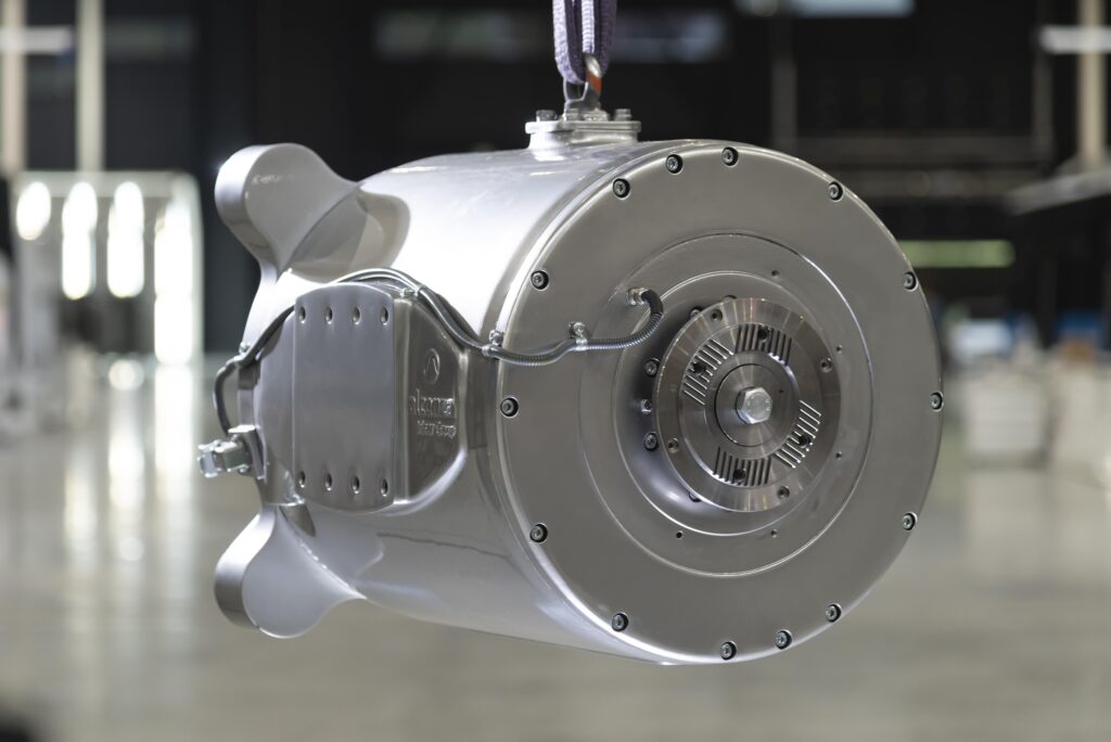
All the motors are permanent magnet three-phase AC machines, and are based on the same design by Alconza and scaled for the pole and magnet count appropriate for each size, although the exact numbers of poles and magnets are undisclosed.
“We weighed up different motor configuration choices, but at the end of the day, synchronous permanent magnet technology yields the biggest torque density and power density figures, and our powertrains and load requirements enable us to work at the most efficient speeds and configurations for PMAC motor designs,” Letona says.
“From our research and observations, asynchronous or inductive motors are most useful when combined with a gearbox so that you can use them at their most efficient operating points and still get the traction outputs you need.
“But we also wanted as compact and lightweight a powertrain as possible, given that we’re already going to be carrying around so much weight in the bin loader and compactor. At the same time, we need to reserve space beneath the chassis for batteries, so we can’t have a gearbox taking up the volume of two or more packs.”
Neodymium magnets are used in the rotor, mounted internal to the rotor rather than on the surface for a more secure hold without having to rely on adhesives. Notably, Irizar has also segmented its magnets, a technique in which magnets are split into several pieces (commonly four) instead of each being a single, solid length. The company’s engineers went with this design approach after finding in their electromagnetic simulations that this would reduce the eddy current losses across the motor’s high-speed operating points.
The stators on the medium and large motors incorporate dual windings, as per NEMA (National Electrical Manufacturers Association) Class H requirements for motors that operate at up to 180 C. Having two sets of windings allows for a more even distribution of current, which prevents concentrations of heat that could exceed the vehicle’s cooling capabilities and enables more torque and power within the NEMA-defined current limits.
Two inverters are therefore installed next to the motor, one for controlling each set of windings. The dual windings are also designed and connected to enable the e-motor to be run correctly with only one inverter for redundancy.
The motors are housed in aluminium, principally to reduce weight, and the enclosure integrates a water-cooling circuit that runs in close contact with the stator. To ease the integration process, the e-motors are connected by means of Powerlock connectors that are designed to withstand the harsh electrical and mechanical conditions faced by heavy EV operations.
Variable-frequency drive control over the truck’s AC traction motor is achieved using three-phase silicon IGBT-based inverters. This DC-AC system weighs 13.9 kg and comes in an IP6K7 or IP6K6 enclosure measuring 475 x 244 x 109 mm, and is designed to operate on a 800 V DC input.
These power converters typically operate at 300-400 A, with a maximum current of 850 A, and Irizar reports that its IGBT technology allows efficiencies of up to 98% across the range of operations. They can also be connected in parallel to increase the current drive capability and pull heavier loads, if such a need is anticipated for the driver’s routes.
Similar components are used for the inverters controlling the generator, ePTO motors, and compressor. They consist of individual modules rated to 30 or 60 kW, and are connected together to meet each PMAC motor’s power requirement.
Each module – referred to in-house as drive converter units (DCUs) – can operate from 800 to 200 V DC inputs to output up to 600 V AC. The 60 kW DCUs output a typical 58 A, up to a maximum of 104 A if set to 180% overload for 10 seconds, while the 30 kW DCUs produce 30 A nominally, or up to 54 A if similarly overloaded. Smaller, 8 kW and 15 kW units are also available for configurations with motors containing very few pole pairs.
Explaining the inverter architectures further, Letona says, “A lower body section contains a pre-tested water cooler and holds the high-voltage connectors. A single PCB is mounted into this section and contains the power stage as well as the control unit. The magnetic elements of the transformer are mounted beside the IGBT modules on the same cooling element, to maximise power density inside these most expensive parts.
“After the power electronics are assembled into the lower body part, the unit is closed with a top cover. After mating the HV and control connectors, the plugs and wiring are protected by an additional metal cover, to decrease the EMI radiation and protect the connectors from the water jets of any high-pressure cleaners used during maintenance. This wiring chamber cover also acts as a disconnection detection device, since its removal can be detected and signalled via CAN bus.”
Application engineering
Working with FCC provided the critical targets, specifications and engineering guidance for the bin loader and compactor. While Irizar’s prior experience with buses was a vital factor in FCC wanting to work with the company, designing for this application departed from its usual projects in a few crucial aspects.
Letona explains, “As well as the high transient power demands for the ie truck, a key difference from buses is that, at a stop, a bus just opens a door to let passengers on and off.
By contrast, the refuse truck has to handle a bin loader and compactor, which are far heavier and more energy-hungry systems than you have on a bus, even accounting for the higher number of HVAC systems for passengers.”
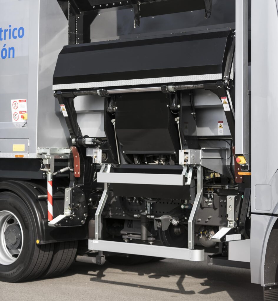
As mentioned, the refuse systems are hydraulically powered to avoid the costs or new inventories of creating an all-new, all-electric loader and compactor. As indicated, an anterior facing permanent magnet AC motor installed at the top of the components cradle drives the hydraulic pump via an SAE-standard driveshaft connected to the pump’s PTO.
“A fixed-frequency drive inverter and control system is used for that motor, and it’s controlled indirectly by the energy management ECU, which sends the power needed for driving the pump as required,” Letona says. “We place it low in the components cradle for easy connection to the pump and to ensure a lower height than the oil tank, thus cavitation is avoided as we always ensure positive pressure in the inlet of the pump.
“Overall, the system is much more energy-efficient than conventional refuse configurations. Diesel-powered trucks must run their IC engine at idle to work the pump – they don’t load bins or compact the waste while moving, as that would drive the pump too hard. That means they’re consuming far more energy than this small pump actually needs.
“Not only are e-motors far more energy-efficient but we can run the compactor while moving, as our traction and loader motors are separate systems. That means workers can compact trash while heading to the next bin site, saving time per day compared with diesel trucks.”
Each loading operation takes 35- 50 seconds, while the total time spent compacting varies greatly depending on the kind and quantity of refuse being collected. The refuse motor is connected to the truck’s liquid-cooling circuits so that its temperature can be normalised if excess heat is being produced from its current draw over time. The pump is designed with two output valves – one for pumping oil to the loader, one for the compactor – and has a single inlet for oil returning from both. The motor outputs the power requirement in line with the flow rates needed to drive either machine. Irizar can also install two motor-pump systems (which are more efficient owing to a more precise control of oil flow) if an end-user prefers separating the drives for either task.
“We have four different motor sizes because, depending on the size of the bins being loaded at the rear or side and the kind of waste collection body that has been built, the required flow rates can change a lot,” Letona adds. “Some companies are building fully electric loaders and compactors, which we would also be able to operate just by powering it using the HV bus and controlling through the 24 V bus.”
Charging options
CCS Type 2 DC fast chargers are installed in the ie truck, as the company has found that more and more end users want the fastest possible charging times.
“We have a wide portfolio of charging systems though, from 20 kW up to 50, 100, 150 and 250 kW plug-in chargers available, and the standard ie truck uses an 80 kW charger that replenishes 350 kWh in just over 4 hours,” Letona says. “Jema Energy can also design end-to-end onboard AC charging for customers who prioritise battery lifespans over charging-related downtime.”
And if selected, the hybrid range extender can generate around 150 kW. It uses a spark-ignited CNG engine from FPT Industrial (a subsidiary of CNH Group), with a PMAC generator mounted onto the crankshaft.
FCC has used CNG in numerous waste management configurations around the world, and was therefore satisfied from early on that this arrangement would be suitable for charging the batteries on some of its trucks without causing diesel-level emissions.
Two steel CNG storage bottles are mounted on the upper rear of the chassis. To make room for them, the battery section is typically smaller compared with the fully electric truck – usually one- or two-thirds smaller – but the maximum energy capacity is kept high enough to cover sufficient city routes to fill up the loader and compactor.
The at means once they’re at capacity for refuse collection, and battery charge is low, they can start the engine on the way to the landfill – or to the depot to swap staff – so that in the 45-90 minutes that the truck is on the highway and far from homes, offices and low emissions zones, the noise and exhaust aren’t bothering anyone,” Letona says. “The generator’s 150 kW output means 30-60 minutes are all that’s needed to fully recharge the batteries – they can be replenished without the workers having to deviate from their routes or schedule.”
He notes also that since the engine is never needed for traction, it can be run at its most fuel-efficient rpm, and at a constant speed without losses from acceleration or deceleration, to ensure the time efficiency gained from the hybrid option is not counter-intuitively offset by fuel costs.
“Incidentally, we’ve installed pantograph chargers on some buses, which are automated and enable opportunity charging throughout the day,” Letona adds. “They can charge at 500-600 kW to quickly replenish energy during short stops, maybe 60- 70% of total capacity within 5 minutes. So pantographs could be installed for the ie truck if the workers have some locations with a lot of bins present where they need to stop for several minutes at a time, like behind a hotel or shopping mall or even at the landfill site for example.”
Energy storage
NMC cells are used in the ie truck’s batteries, for their high energy density and power density relative to other chemistries, as well as their high number of cycles. That helps to minimise the number of pack replacements needed over each truck’s 8-10 year lifetime, given that the packs tend to form the largest expense for EVs.
Irizar uses pouch-type as well as prismatic cells. The former are better for energy density owing to their compact shape and how tightly they can be stacked together, while the latter are better suited to repeated charging and discharging without significant loss of lifespan (in terms of total capacity lost or lithium dendrites manifested over time).
“The superior cyclability and C-rates of pouch cells made them the ideal choice for the first ie trucks, in terms of how FCC was going to use the EVs, but of course we’ll change the cell choice to give the best pack for each vehicle and route,” Letona says.
“To ensure we’re making informed cell choices and keeping aware of different battery technologies out there, we’ve been collaborating with the CIDETEC research centre here in the Basque Country since 2014,” he adds. “It experiments with and even produces different cell configurations with many chemical variations. It has been indispensable in helping us gain ‘battery independence’ in terms of the knowhow to construct and optimise our own packs.”
The voltage of Irizar’s packs is variable. At the moment they can be designed for a high-voltage bus of up to 800 V, which the company views as the most desirable level right now for frequent fast charging, both for avoiding excessively high current and therefore heat, and for being able to easily develop or acquire components designed for this operating voltage.
“Depending on the running charge of the batteries, the operating voltage in the ie truck runs at between 550 and 800 V DC,” Letona says. “In the 100%-electric version, we install 340 kWh across four packs.”
Thermal management
Each battery pack has its own aluminium cooling plate for ensuring a uniform temperature distribution across the cells as heat is conducted out to the coolant. The thermal behaviours, as well as the electrical and physical characteristics, have been modelled extensively in-house.
As Letona explains, “We created simulation tools in MATLAB to emulate the behaviours of our batteries and power electronics under customised load profiles, recreating both hybrid and fully electric working conditions based on data gathered in several cities and applications as well as models for battery ageing and dynamics derived from in-house cell testing.”
The simulations included finite element methods such as structural statics including shock and endurance tests, and structural dynamics including calculations of natural frequencies and transmissibility of external forces.
The thermal homogeneities of the cooling plates and battery modules are also plotted via flux calculations, with pressure losses of the circuits and maximum and minimum temperatures of each of the remaining components also having been studied.
The battery modules integrate materials for thermal conductivity and electrical insulation to avoid concentrating and building up heat inside the cells, while thermal insulation material is installed at the pack level (inside the walls of each face of the pack enclosures) to protect the packs’ insides from harsh environments outside.
“Lithium is very sensitive to temperature extremes, so for energy efficiency and safety we have a target temperature of 25 C,” Letona says.
“Low temperatures are the biggest challenge for this; it’s easy for them to go below 0 C during winter, not just in Spain but especially in France and the UK. There are different solutions for that, but the optimum one is having the vehicle draw all the electricity required for warming the batteries from the charger/grid when stationary. That means batteries are warmed up but still at 100% capacity when the truck’s work is about to start.
“High-quality thermal insulation at the pack level is really important for keeping the cold out of the packs and for ensuring that the heat produced by the cells can actually stay inside the packs and warm up those spaces to around 25 C. It also means our HVAC’s heater system needs to consume less energy to heat the batteries.”
As mentioned, a radiator is installed in the inlet above the cabin for cooling the liquid circuits in the ie truck; three water-glycol circuits are installed. The first of these runs between the cabin and battery packs, an efficient choice as both need their environments to be maintained at roughly 25 C (a point also noted by Designwerk in its Futuricum truck, as described in EME 8, Winter 2020).
The second circuit is used for cooling the electronic and electric systems – the ECUs, inverters, DC-DCs and motors – owing to the sharp temperature gradients these components can produce during operation.
“The third liquid circuit is essentially a safety circuit, which also runs through the components cradle, and is activated in the event of overvoltage or some other problem,” Letona explains. “Basically it’s so that if there’s an accident or malfunction generating excess heat, we have an extra level of back-up cooling in place.”
Future plans
As mentioned, the ie truck is now operating across France and Spain, from Badajoz where temperatures reach 42 C, to Nantes, which experiences winters of -10 C. While the Covid pandemic temporarily slowed its expansion plans, as mechanics and technicians were prevented from going to their workplaces, Irizar Group is now resuming talks to provide the truck to users across northern Europe, including Germany, Austria and Switzerland. In addition to the two configurations currently available, Irizar has also designed an eight-wheel, four-axle ie truck to handle larger and heavier loads, enabling their EVs to be used by commercial fleet operators in some of the largest cities in the world.
Some key suppliers
Motors: Alconza
Batteries: in-house
Battery consultation: CIDETEC
Inverters: Jema Energy
Chargers: Jema Energy
DC-DC converters: Jema Energy
DC-DC converters: Lenze
HVAC: Hispacold
Accessibility systems: Masats
Data management and connectivity
systems: Datik
High-voltage cables: in-house
High-voltage cables: undisclosed
Specifications
ie truck
Battery-electric or CNG series hybrid
Permanent magnet AC motor
NMC pouch-type cells
4 x 2 wheel
Two-axle
Weight: 10.5 t
Maximum energy: 340 kWh
Maximum range: 250 km
Maximum power: 160 kW
Maximum operating torque: 3000 Nm
Charging time: Up to 2 hours at 150 kW
6 x 2 wheel
Three-axle
Weight: 12.5 t
Maximum energy: 340 kWh
Maximum range: 250 km
Maximum power: 240 kW
Maximum operating torque: 3600 Nm

